Hello everyone!
For the past several weeks I have been working on a big project, and simultaneously my first and true mechanical project that demanded great persistence and work, and now when it is finally finished, I would like to share it with you. This project is about a Monorail crane, which transport capacity is 2 tons, and on which the lifting mechanism moves. Each mechanical project must include the following items:
- Technical description of the construction
- Movement and deformation calculations
- Calculation of allowed voltages - calculation of strengths
- Technical documentation of the construction
In this article, I will present you briefly each of the aforementioned items, respectively, you will have an insight into that, how a project that the engineer needs to process is really looking, in order to further import it into the reality, and to do the job for which it is foreseen. First of all, I would like to emphasize that 80% of the project was done in CATIA and SAP2000, which are well known programs for all mechanical engineers. Of course, there are still many programs for 3D and 2D modeling and determination of deformation of structures, and it is absolutely your choice in which program you want to process and import your solution. I will begin with the technical description of the construction.
1. Technical description- Project Monorey crane with a capacity of 2 tons
Monorail cranes consist of 3 P-RAMS connected by longitudinal carrier on which the lifting and lowering mechanism moves. All three P-frames are fixedly attached to the substrate. Three different profiles were applied on the construction, which are of course standardized and those are HEA180(I-profile), 140x140x5.6(box profile) and HEM140(also I profile). Below you can see a 3D view of a whole crane as well as a 3D view of each of the used profiles.
https://steemitimages.com/DQmaewL5vHU4GcNqHDz1RZDdDz7KhDgDkFXyVVS2vD4ZwrP/redner%207.jpg
Monorail crane
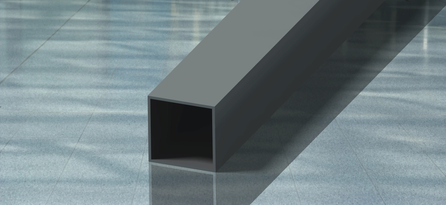
Profile 140x140x5,6
https://steemitimages.com/DQmX8AibLyKAVUMqohLog4PxcQBi4V8ceLAKDy2ZHkmJyqX/RENDER%203%20jpg.jpg
Profile HEA180
The profiles HEA180 and HEM140 in the image look the same, so I'll show you the look of just one of them.
2. After the technical description, we are going to determine the DEFORMATION
Namely, this is a very simple job if you do it in the American SAP2000. Draw your construction simplified in the form of rods, from several segments (joints and elements), set the above profiles (HEA 180, 140x140x5, 6, and HEM 140 ), set some load in a number of different points, and the program shows itself how the whole construction deforms. This program gives you the exact values of each shift for each load case, so you can read every millimeter of movement of construction from this program. In the illustrated photos you will be able to see 3 load cases, respectively, 20 tons of cargo placed in 3 different positions, as well as how the SAP2000 sees this mechanical circuit.
The first case of load
The second case of load
And the third case of load
And now I will show you only one of the many tables with the information that gives you SAP2000, and in which you can see all the moments and forces that burden your construction in 3 different axes.
3. Calculation of allowed voltages - calculation of strengths
This part of the project is done manually. Since my construction is made of steel S235 (standard construction steel), we read its tensile strength, multiply it with a degree of safety and get the permissible voltage for the construction. A large length of construction causes the bending voltage, which occurs between the supports, so we need to check if this voltage is greater than the permitted, as you will see below. If it is, your construction will not satisfy certain strength - it will go down . If the calculation does not satisfy, you need to take stronger profiles . Formulas for checking the voltages you can see below.
4. Technical documentation
Technical documentation is placed at the end of each project, which does not make it less important than the rest. In the technical documentation, you are doing precise drawings of your construction, assembly, and each part separately. The documentation includes the number of pieces that are being created, the dimensions of each element are given, the name of the Investor , your name as a name of the constructor, and of course all of this is done in a somewhat reduced scale, so that your entire idea could fit into one paper. Documentation is most often made on A4, A3 and A2 paper formats, so that the drawing is as transparent as possible. Below I will show you 2 examples of technical documentation preparation on A3 and A4 paper formats.
The idea of this whole project of Monorail crane I was working on was to fit this construction into water wells, so a mechanism for lifting and lowering could move on carrier and take the load from the well. This constructions are highly applicable throughout the world.
One important note
All contacts between frames on the structure and between frames and their fixed supports were realized with welded joints, while the connection with the substrate was achieved by a screw connection (M16 screw).