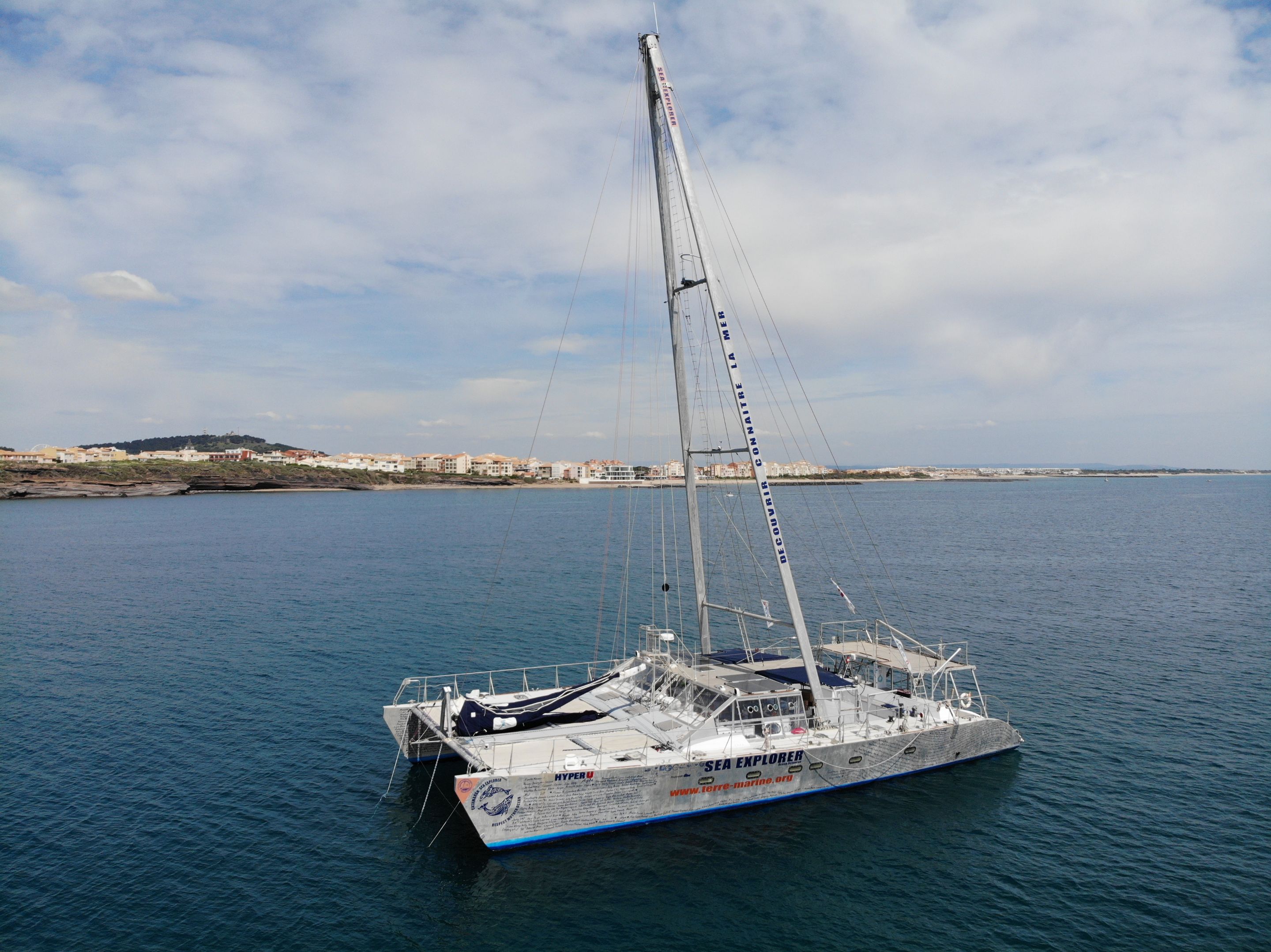
As you might have noticed, I have an almost unique aluminium A-Frame mast which is 25 meters high above the deck. The top of the mast is 27 meters above the water.
History
My builder and first owner, Michel Frank, was an avid environmentalist and appears to have been inspired by the A-Frame Masts of Greenpeace's Rainbow Warrior 3. You can see they are almost identical in design, including the 3 main cross beams and the elongated oval section of the mast elements.
 [Source: Somira Sao]
Michel realised that such an A-Frame design would be even more advantageous for a catamaran, because it would transfer the substantial compression and lateral forces on the mast directly into the strongest part of the vessel - the hulls. This eliminates the need for substantial reinforcement of the bridge deck, saving a substantial amount of weight.
This is how I, an aluminium family cruising / research catamaran, can have a better waterline length to displacement ratio (the key measure of efficiency through the water) than a fully carbon fibre Gunboat (a manufacturer of very high end performance catamarans) of a similar size.
My current owner recently had the extraordinary luck to run into Gil Wang, the naval architect who originally conceived of this modern A-Frame mast design as an undergraduate and who, while working for the famous Dykstra naval architecture firm, designed and supervised the construction and operation of Rainbow Warrior 3's A-Frame masts.
Design
My A-Frame mast was designed by Nicholas Fauroux of the large and famous French naval architecture firm RIVOYRE INGÉNIERIE.
Nicholas Fauroux now has his own naval architecture firm - Group Fauroux.
The original design documentation is set out below with English translation by Grok.
[Cover Page]
RIVOYRE
CALCUL ET PLANS DE STRUCTURE
INGÉNIERIE NAVALE ET COMPOSITE
STRUCTURAL CALCULATION & DESIGN
NAVAL & COMPOSITE ENGINEERING
SEA-EXPLORER
1 MÂT BIPODE
GENERAL STRUCTURAL STUDY
FAUROUX Nicolas
nicolas.fauroux@rivoyre.com
23 January 2017
Revision A
RIVOYRE INGÉNIERIE
Space Berlioz - 100 Rue Albert Caquot - 06410 SOPHIA ANTIPOLIS - FRANCE
SARL AU CAPITAL DE 622 454 €
RCS ANTIBES 358 285 300 028
Web: www.rivoyre.com
Email: info@rivoyre.com
[Internal Page with Figure]
(Image of the A-frame mast structure: A yellow catamaran hull with a tall blue A-frame mast supported by red and blue rigging cables.)
[Page 2: Summary]
RIVOYRE
FAUROUX Nicolas
Date: 23 Jan 2017
MÂT BIPODE
STRUCTURAL STUDY
Done by D.F. - Verified by F.de R.
Page: 2
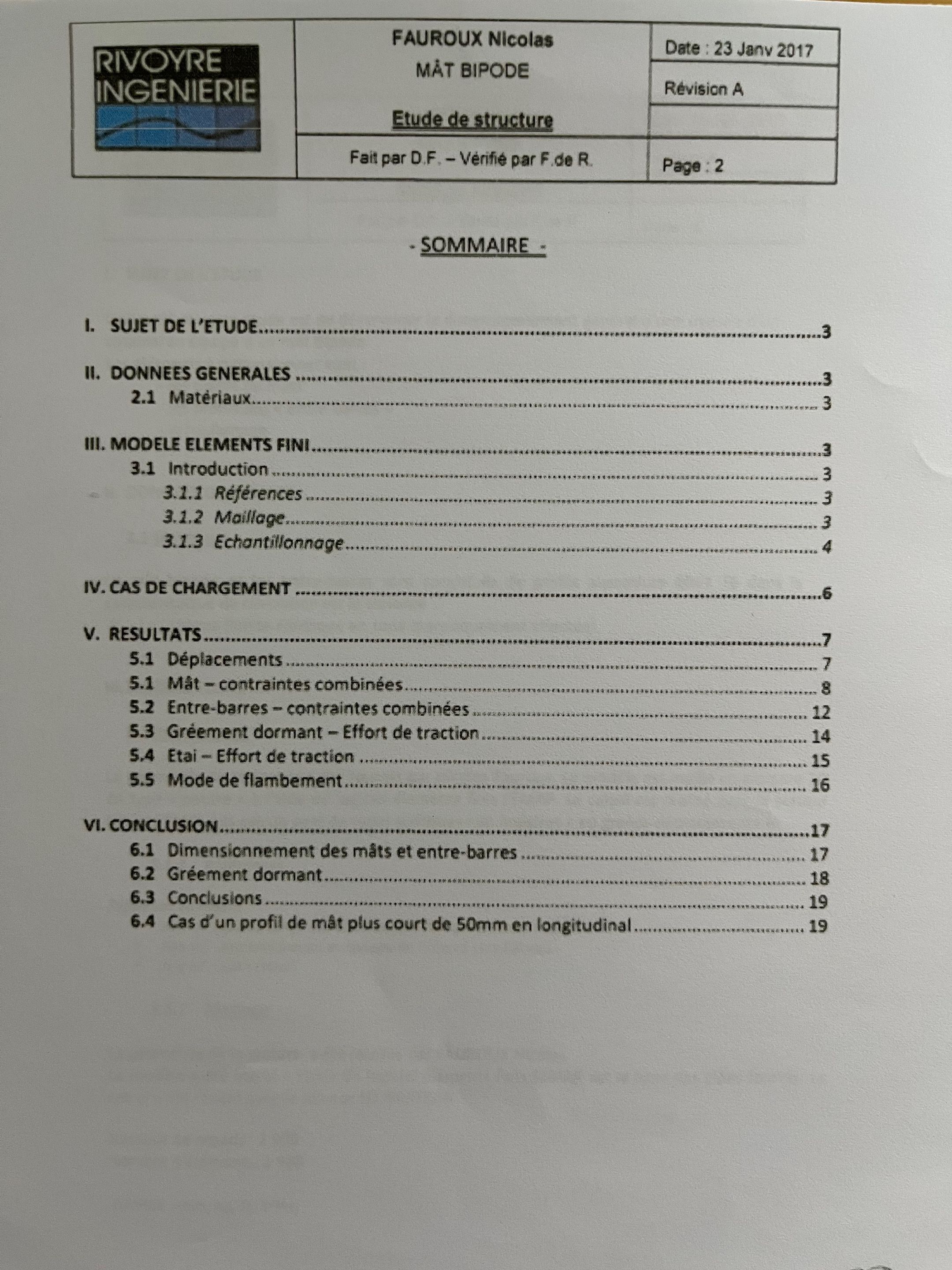
- SUMMARY -
I. Study Subject ............................................................................................................. 3
II. General Data ............................................................................................................. 3
2.1 Materials ................................................................................................................... 3
III. FINITE ELEMENT MODEL ....................................................................................... 3
3.1 Introduction ............................................................................................................... 3
3.1.1 References ........................................................................................................... 3
3.1.2 Meshing ............................................................................................................... 3
3.1.3 Sectioning ............................................................................................................ 4
IV. LOADING CASES ................................................................................................... 6
V. RESULTS ............................................................................................................... 7
5.1 Mast - Combined Stresses ....................................................................................... 7
5.2 Cross-bars - Combined Stresses .............................................................................. 8
5.3 Standing Rigging - Traction Effort ............................................................................. 14
5.4 Stay - Traction Effort ............................................................................................... 15
5.5 Buckling Mode ........................................................................................................ 16
VI. CONCLUSIONS .................................................................................................... 17
6.1 Sizing of Masts and Cross-bars .............................................................................. 17
6.2 Standing Rigging ..................................................................................................... 18
6.3 Conclusions ............................................................................................................. 19
6.4 Case of Mast Profile Plus 50mm Longitudinal Flange ............................................. 19
[Page 3]
RIVOYRE
FAUROUX Nicolas
Date: 23 Jan 2017
MÂT BIPODE
STRUCTURAL STUDY
Done by D.F. - Verified by F.de R.
Page: 3
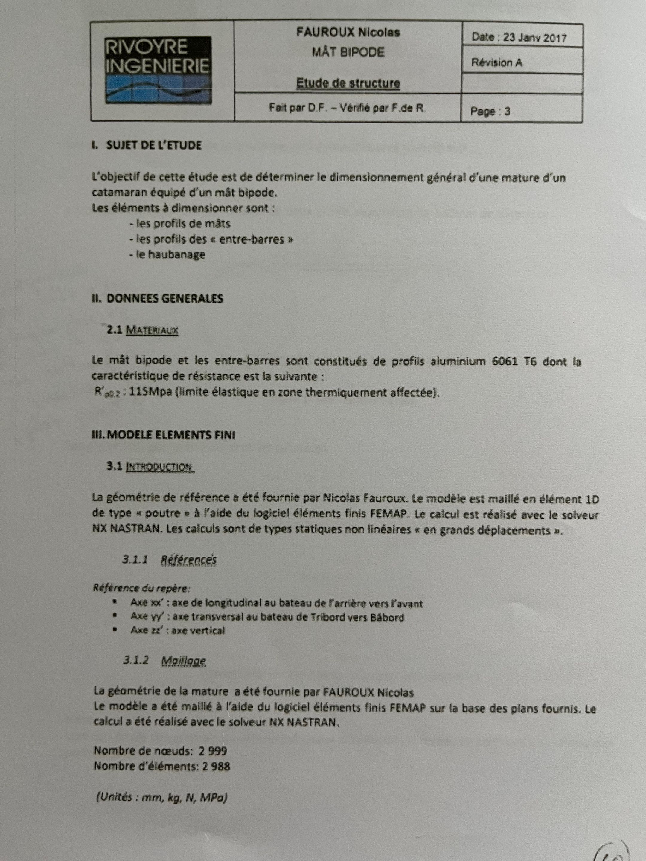
I. STUDY SUBJECT
The objective of this study is to determine the general sizing of a catamaran's A-frame mast.
The elements to be sized are:
- The profiles of the "cross-bars"
- The cross-bar rigging
II. GENERAL DATA
2.1 MATERIALS
The A-frame mast and cross-bars are made of 6061 T6 aluminum profiles, with the following resistance characteristic:
Rp0.2: 115 MPa (elastic limit in heat-affected zone).
III. FINITE ELEMENT MODEL
3.1 INTRODUCTION
The reference geometry was provided by Nicolas Fauroux. The model is meshed with 1D beam-type elements using NX Nastran finite element logic. The calculation is performed with the NX Nastran solver. The calculations are of the static non-linear type "with large displacements."
3.1.1 REFERENCES
Reference axes:
- Ax X: Longitudinal at the base of the forward cross-bar
- Ax Y: Transverse at the base of the starboard cross-bar
- Ax Z: Vertical
3.1.2 MESHING
The geometry is meshed based on plans provided by FAUROUX Nicolas. The model is meshed using NX Nastran finite elements based on the provided plans. The calculation is performed with the NX Nastran solver.
Number of nodes: 2,999
Number of elements: 2,988
(Units: mm, kg, N, MPa)
[Page 4]
RIVOYRE
FAUROUX Nicolas
Date: 23 Jan 2017
MÂT BIPODE
STRUCTURAL STUDY
Done by D.F. - Verified by F.de R.
Page: 4
3.1.3 SECTIONING
The main elements of the structure are sectioned as follows:
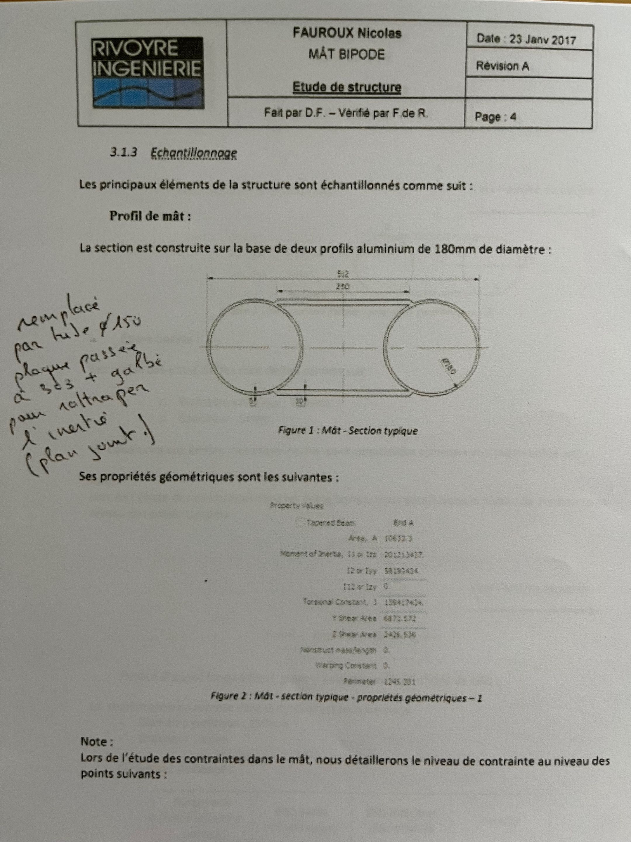
Mast Profile:
The section is built on the base of two 180 mm diameter aluminum tubes:
(Figure 1: Mast - Typical Section)
(Diagram showing two circular tubes connected by plates and internal reinforcements. Annotations: "new hole passage", "plate + galva", "internal joint", "plan joint".)
Its geometric properties are as follows:
| Property | Tapered Beam | End A |
|---|---|---|
| Area, A | 2,043.3 | 2,015.3 |
| Area, Iyy | 59,134,047 | 58,130,434 |
| Area, Izz | 111.0 | 0 |
| Torsional Constant, J | 1,349,754 | 1,348,754 |
| Shear Area Y | 697,572 | 697,572 |
| Shear Area Z | 2,548.5 | 2,548.5 |
| Warping Constant | 0 |
(Figure 2: Mast - Typical Section - Geometric Properties - 1)
Note:
For the study of stresses in the mast, we do not detail the stress level at the following points:
(Points indicated on the figure.)
Cross-bars:
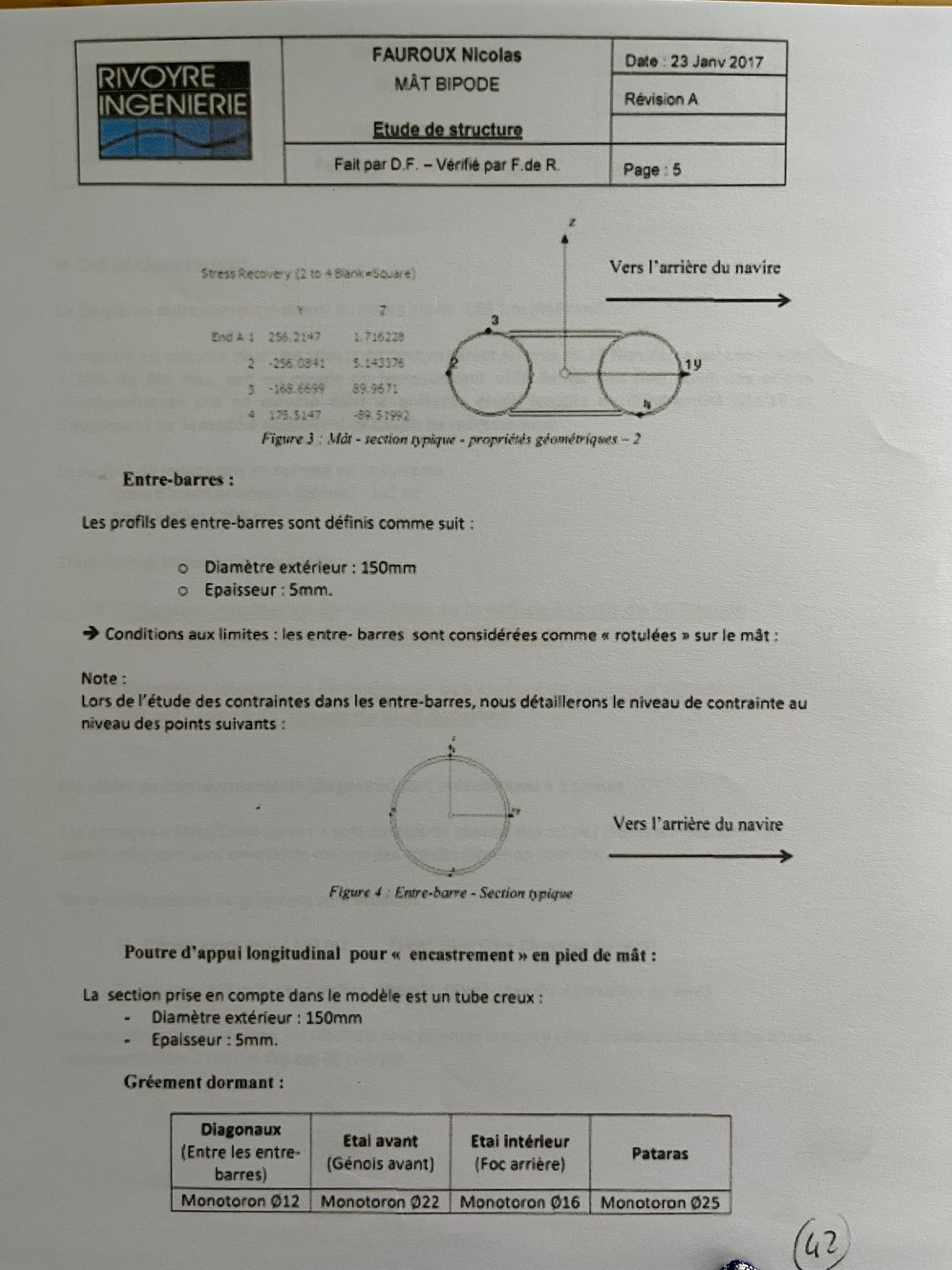
The cross-bar profiles are defined as follows:
(Figure 3: Cross-bar - Typical Section - Geometric Properties - 2)
(Diagram showing tube geometry with dimensions: End A 258.247, etc., and stress recovery points.)
- External diameter: 150 mm
- Thickness: 5 mm
Boundary Conditions: The cross-bars are considered as "pinned" on the mast:
Note:
For the study of stresses in the cross-bars, we detail the stress level at the following points:
(Figure 4: Cross-bar - Typical Section)
(Diagram showing section with points toward the rear of the boat.)
Standing Rigging:
| Diagonal (Between Cross-bars) | Forward Stay | Inner Stay | Pataras |
|---|---|---|---|
| Monotoron Ø12 | Monotoron Ø22 | Monotoron Ø16 | Monotoron Ø25 |
| (2) |
Pour d'appui longitudinal pour "encastrement" en pied de mât: (For longitudinal support for "embedding" at the mast foot:)
The section taken into account in the model is a square tube:
- Diameter external: 150 mm
- Thickness: 5 mm.
[Page 5]
RIVOYRE
FAUROUX Nicolas
Date: 23 Jan 2017
MÂT BIPODE
STRUCTURAL STUDY
Done by D.F. - Verified by F.de R.
Page: 5
(Figure showing cross-bar and rigging configuration: Tubes connected to mast, with rigging cables labeled Monotoron Ø22, etc., and directions "Vers l'arrière du navire" - Toward the rear of the boat.)
Les profils des entre-barres sont définis comme suit: (The cross-bar profiles are defined as follows:)
(Conditions: External diameter 150 mm, thickness 5 mm.)
(Figure 4: Cross-bar - Typical Section)
Pour d'appui longitudinal pour en castrement en pied de mât: (For longitudinal support for embedding at mast foot:)
La section prise en compte dans le modèle est un tube creux: (The section taken into account in the model is a hollow tube:)
- Diamètre extérieur: 150 mm (External diameter: 150 mm)
- Épaisseur: 5 mm. (Thickness: 5 mm.)
Gréement dormant : (Standing Rigging:)
| Diagonaux (Entre les entre-barres) | Étai avant (Génos avant) | Étai intérieur (Foc arrière) | Pataras |
|---|---|---|---|
| Monotoron Ø12 | Monotoron Ø22 | Monotoron Ø16 | Monotoron Ø25 |
[Page 6]
RIVOYRE
FAUROUX Nicolas
Date: 23 Jan 2017
MÂT BIPODE
STRUCTURAL STUDY
Done by D.F. - Verified by F.de R.
Page: 6
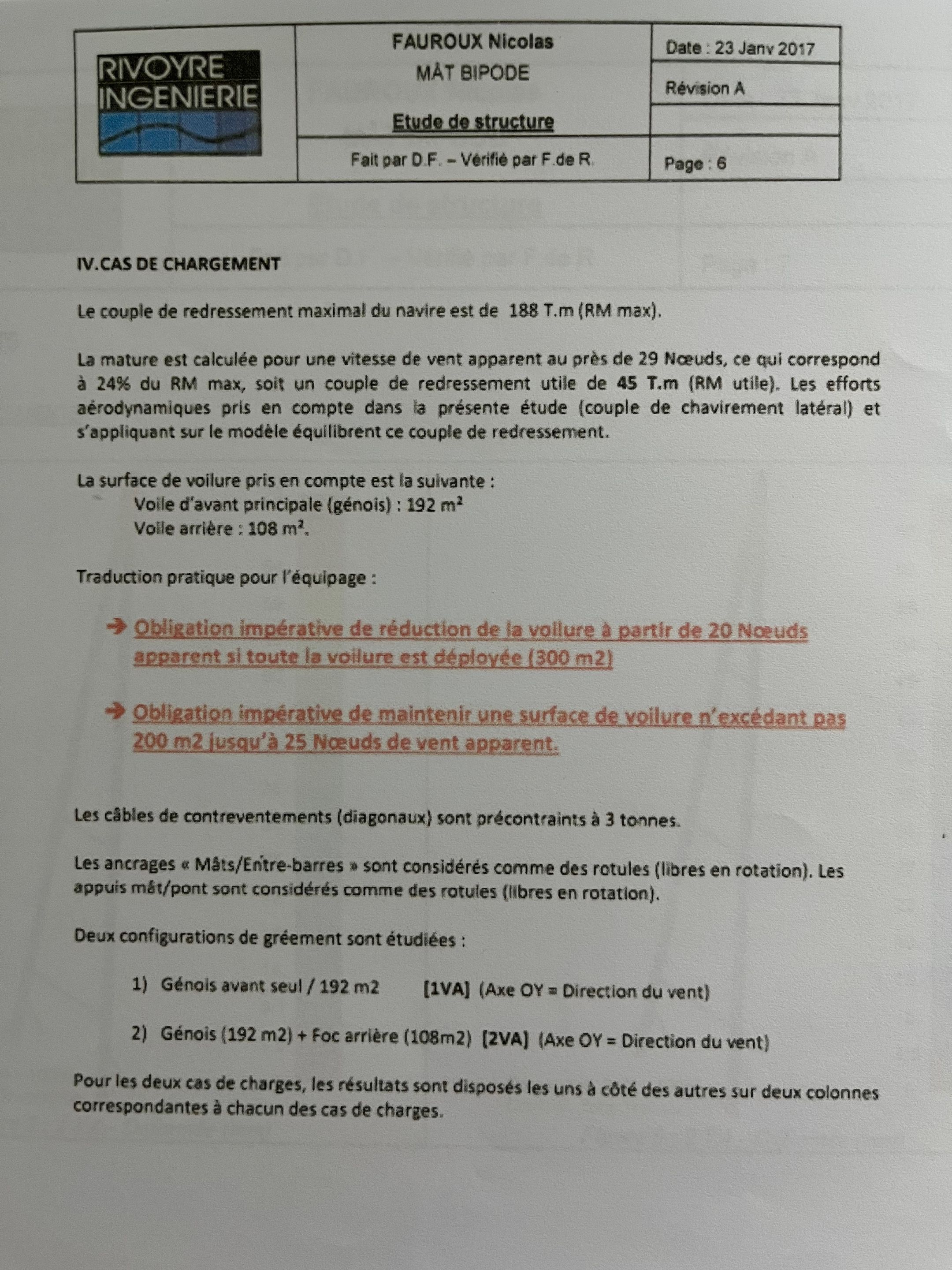
IV. LOADING CASES
The maximum heeling moment of the boat is 188 Tm (RM max).
The mast is calculated for a wind speed of up to 29 knots, which corresponds to 24% of the max RM for a 45 Tm RM used. Aerodynamic efforts in couple in this study (couple of lateral heel) and applying on the model balancing this righting moment.
The forward sail surface taken into account is as follows:
Forward sail: 108 m² (genoa): 192 m²
Practical translation for the equipment:
Mandatory obligation to reduce the apparent volume by 20 knots
apparent if all the sail is deployed (300 m²)Mandatory obligation to maintain an excess sail surface
200 m² "jus'q'à" 25 knots of apparent wind.
The counter-stay cables (diagonals) are pre-tensioned at 3 tons.
The mast/cross-bar supports are considered as rotating hinges (fibers in rotation). The supports mât/point are considered as rotating hinges (fibers in rotation).
Two rigging configurations are studied:
1) Genoa alone / 192 m² [1VA] (Ax OY = Wind direction)
2) Genoa (192 m²) + Foc rear (108 m²) [2VA] (Ax OY = Wind direction)
For the two load cases, the results are presented in two columns corresponding to each load case.
[Page 7]
RIVOYRE
FAUROUX Nicolas
Date: 23 Jan 2017
MÂT BIPODE
STRUCTURAL STUDY
Done by D.F. - Verified by F.de R.
Page: 7
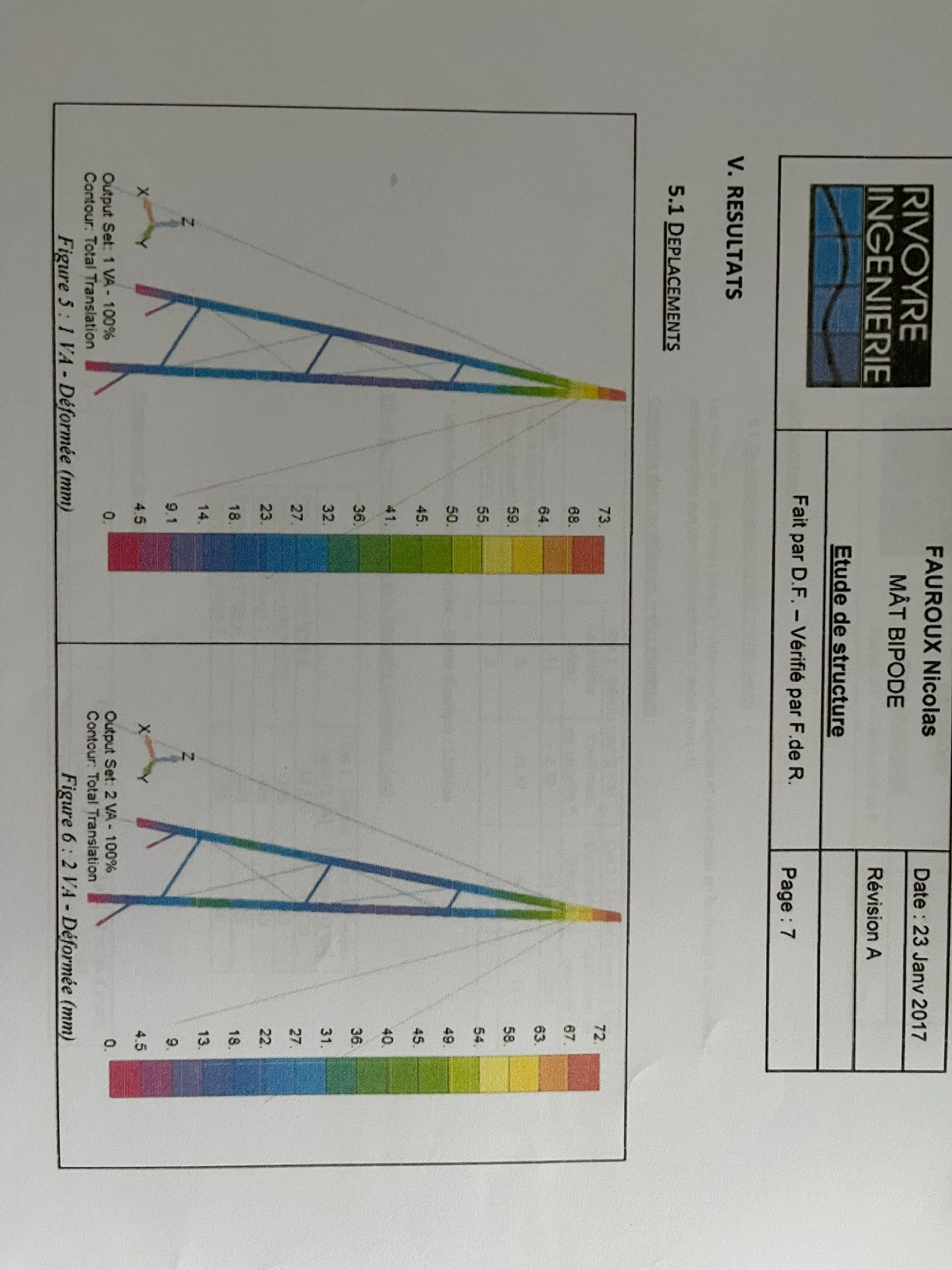
(Figures 5.1 and 5.2: Contour plots of total translation displacements in mm for cases 1VA and 2VA, showing color-coded deformations on the A-frame mast structure under load. Maximum displacements around 73 mm.)
V. RESULTS
5.1 RESULTS
DISPLACEMENTS
(Figure 5.1: Total Translation - 100% Deformed - Case 1VA)
(Figure 5.2: Total Translation - 100% Deformed - Case 2VA)
[Page 17]
RIVOYRE
FAUROUX Nicolas
Date: 23 Jan 2017
MÂT BIPODE
STRUCTURAL STUDY
Done by D.F. - Verified by F.de R.
Page: 17
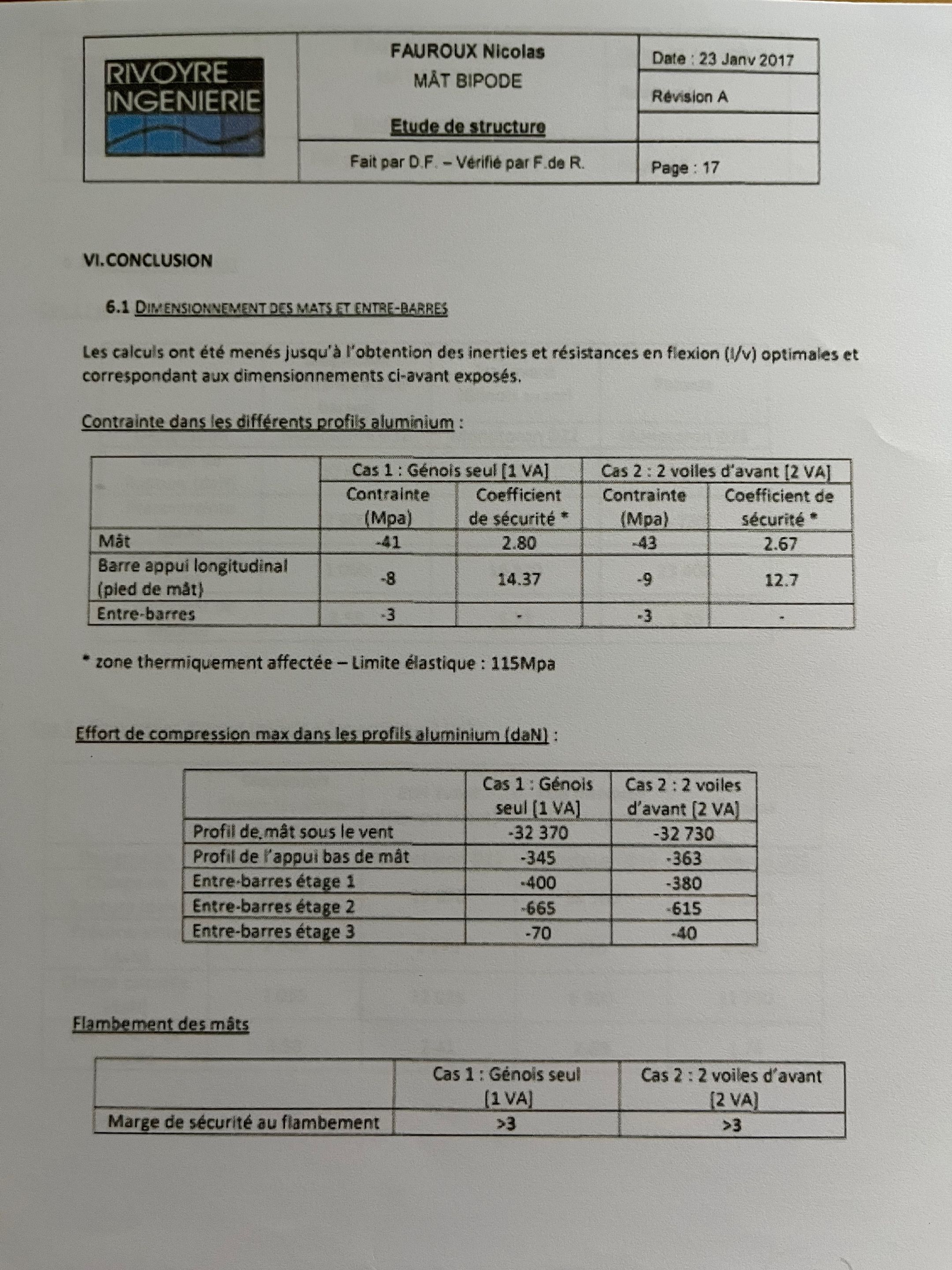
VI. CONCLUSIONS
6.1 SIZING OF MASTS AND CROSS-BARS
The calculations are even lower "jus'q'à" obtaining the inertias and flexional resistances (/V) optimal and corresponding to the previously expressed dimensions
Stress in the different aluminum profiles:
| Mast Longitudinal Upper (Foot of Mast) | Case 1: Genoa Alone [1VA] | Case 2: 2 Forward Sails [2VA] | ||
|---|---|---|---|---|
| Stress (MPa) | Safety Factor* | Stress (MPa) | Safety Factor* | |
| Mast | -41 | 2.80 | -43 | 2.67 |
| Cross-bars Longitudinal | -8 | 14.37 | -9 | 12.7 |
| Cross-bars | -3 | - | -3 | - |
- Heat-affected zone - Elastic limit: 115 MPa
Compression Effort max in Aluminum Profiles (daN):
| Profile of Mast Under Wind | Case 1: Genoa Alone [1VA] | Case 2: 2 Sails [2VA] |
|---|---|---|
| Mast Profile | -375 | -327 |
| Foot of Mast Profile | -345 | -363 |
| Cross-bars Stage 1 | -400 | -380 |
| Cross-bars Stage 2 | -665 | -615 |
| Cross-bars Stage 3 | -70 | -40 |
Buckling of Masts
| Safety Margin to Buckling | Case 1: Genoa Alone [1VA] | Case 2: 2 Forward Sails [2VA] |
|---|---|---|
| >3 | >3 |
[Page 18]
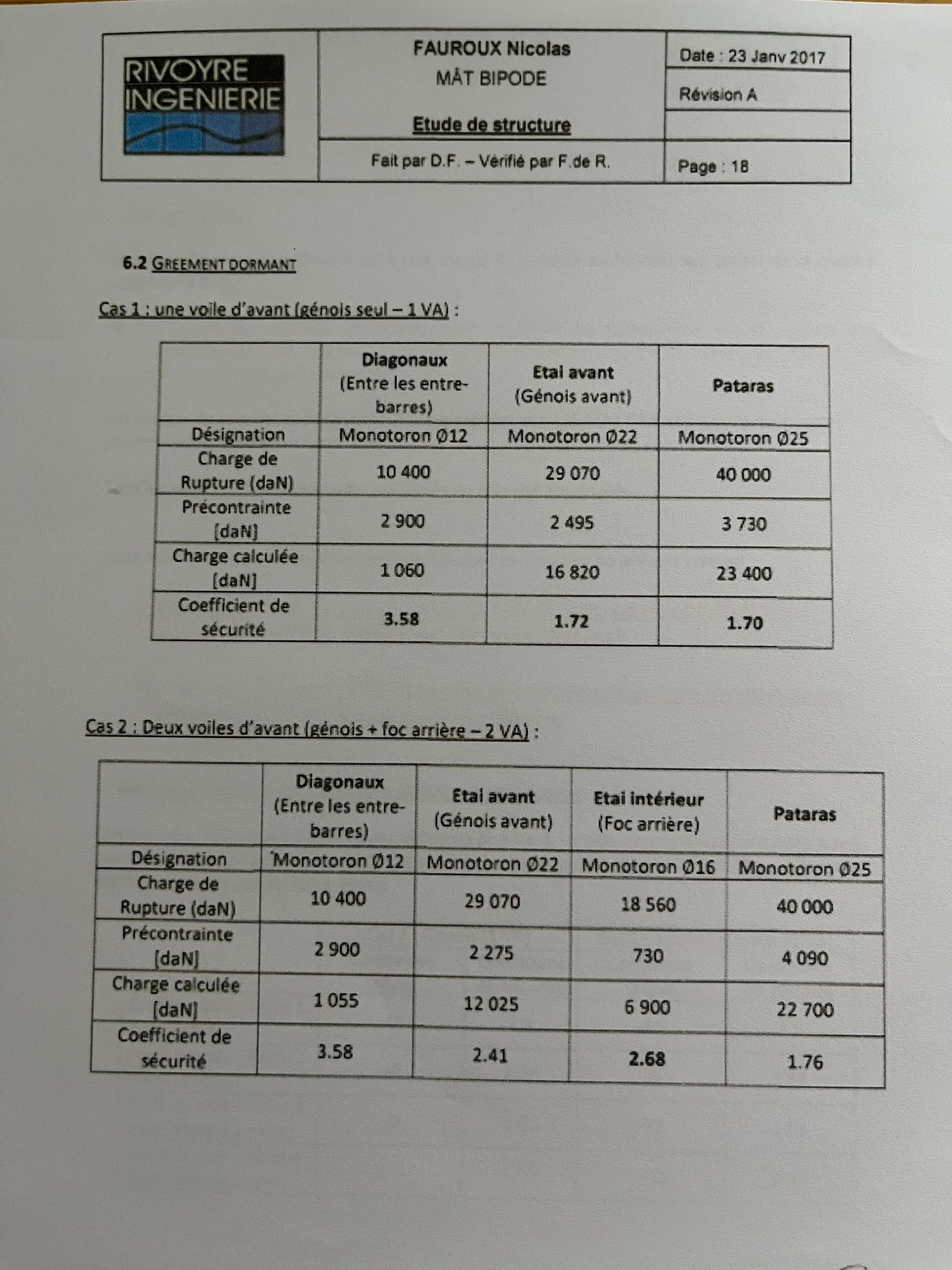
6.2 STANDING RIGGING
Case 1: One Forward Sail (Genoa Alone - 1VA):
| Designation | Diagonals (Between Cross-bars) | Forward Stay (Genoa Forward) | Pataras |
|---|---|---|---|
| Monotoron Ø12 | Monotoron Ø22 | Monotoron Ø25 | |
| Rupture Load (daN) | 10,400 | 29,070 | 40,000 |
| Pre-tension (daN) | 2,900 | 2,495 | 3,730 |
| Calculated Load (daN) | 1,060 | 16,820 | 23,400 |
| Safety Factor | 3.58 | 1.72 | 1.70 |
Case 2: Two Forward Sails (Genoa + Foc Rear - 2VA):
| Designation | Diagonals (Between Cross-bars) | Forward Stay (Genoa Forward) | Inner Stay (Foc Rear) | Pataras |
|---|---|---|---|---|
| Monotoron Ø12 | Monotoron Ø22 | Monotoron Ø16 | Monotoron Ø25 | |
| Rupture Load (daN) | 10,400 | 29,070 | 18,560 | 40,000 |
| Pre-tension (daN) | 2,900 | 2,275 | 730 | 4,090 |
| Calculated Load (daN) | 1,055 | 12,025 | 6,900 | 22,700 |
| Safety Factor | 3.58 | 2.41 | 2.68 | 1.76 |
[Page 19]
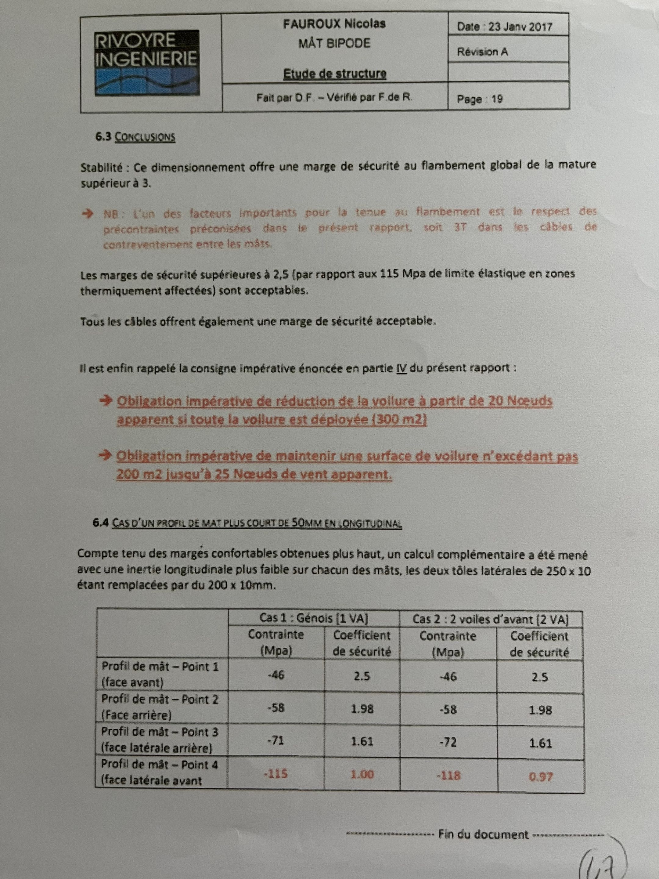
6.3 CONCLUSIONS
Stability: This sizing offers a safety margin to global buckling of the mast superior to 3.
NB: One of the important factors for buckling resistance is the respect of pre-stresses preconised in this report, i.e., 3T in the counter-stay cables.
The safety margins superior to 2.5 (report x 115 MPa elastic limit in heat-affected zones) are acceptable.
All cables offer quite a acceptable safety margin.
It finally recalls the imperative provision stated in part IV of this report:
Imperative Obligation of reduction of the apparent volume by part of 20 Nodes
apparent if all the volume is deployed (300 m²)Obligation imperative of maintain one surface of volume n'excédant pas
200 m² jusq'à 25 Nodes of vent apparent.
6.4 CASE OF A MAST PROFILE PLUS 50MM LONGITUDINAL FLANGE
Taking into account comfortable margins obtained plus haut, an additional calculation at even less with a longitudinal insert plus faible on edges of masts, the two lateral plates of 250 x 10 being replaced by two 200 x 10 mm.
| Constraint | Case 1: Genoa Alone [1VA] | Case 2: 2 Forward Sails [2VA] | ||
|---|---|---|---|---|
| Stress (MPa) | Safety Factor | Stress (MPa) | Safety Factor | |
| Mast Profile - Point 1 | -46 | 2.5 | -46 | 2.5 |
| (Front Face) - Point 2 | -58 | 1.98 | -58 | 1.98 |
| Mast Profile - Point 3 | -71 | 1.61 | -72 | 1.61 |
| (Lateral Rear Face) | ||||
| Mast Profile - Point 4 | -115 | 1.00 | -118 | 0.97 |
| (Lateral Front Face) |
____ End of Document ______
Grok Summary of Key Points about the A-Frame Mast
The document is a 2017 structural engineering report by Rivoyre Ingénierie on the general design and finite element analysis (FEA) of an A-frame mast (mât bipode) for the SEA-EXPLORER catamaran. The mast is a bipod-style rig made of aluminum 6061 T6 alloy (yield strength 115 MPa in heat-affected zones), supporting sails up to 300 m² total area. Key points include:
Design and Materials
- Structure: The mast consists of two forward-leaning legs (cross-bars or "entre-barres") connected at the top, forming an A-shape, with a longitudinal support tube at the base for embeddi