~~~ La versione in italiano inizia subito dopo la versione in inglese ~~~
ENGLISH

13-08-2025 - Mechanics - Kinematic Pairs [EN]-[IT] With this post, I would like to provide a brief introduction to the topic mentioned above. (code notes: X_94)
Kinematic Pairs
Image created with artificial intelligence, ChatGPT software used
Introduction
Today we introduce the concept of kinematic pairs. In applied mechanics, kinematic pairs are connecting devices that allow relative motion between two bodies, but impose constraints that limit their reciprocal degrees of freedom. Kinematic pairs can be: - A rotary joint - A translating joint - A helical pair - A spherical pair - A cylindrical pair - A prismatic pair - A sliding guide - A rolling guide
We can also say that a pair is a system consisting of two adjacent, connected members: if there is relative motion between them (i.e., the system has at least one degree of freedom), it is a kinematic pair.
Below is an image with the example of a prismatic pair, a sliding guide, and a rolling guide.
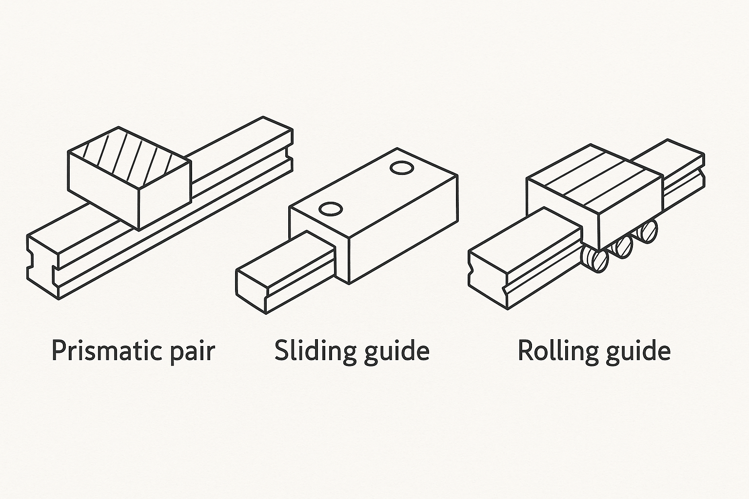
Image created with artificial intelligence, the software used is ChatGPT
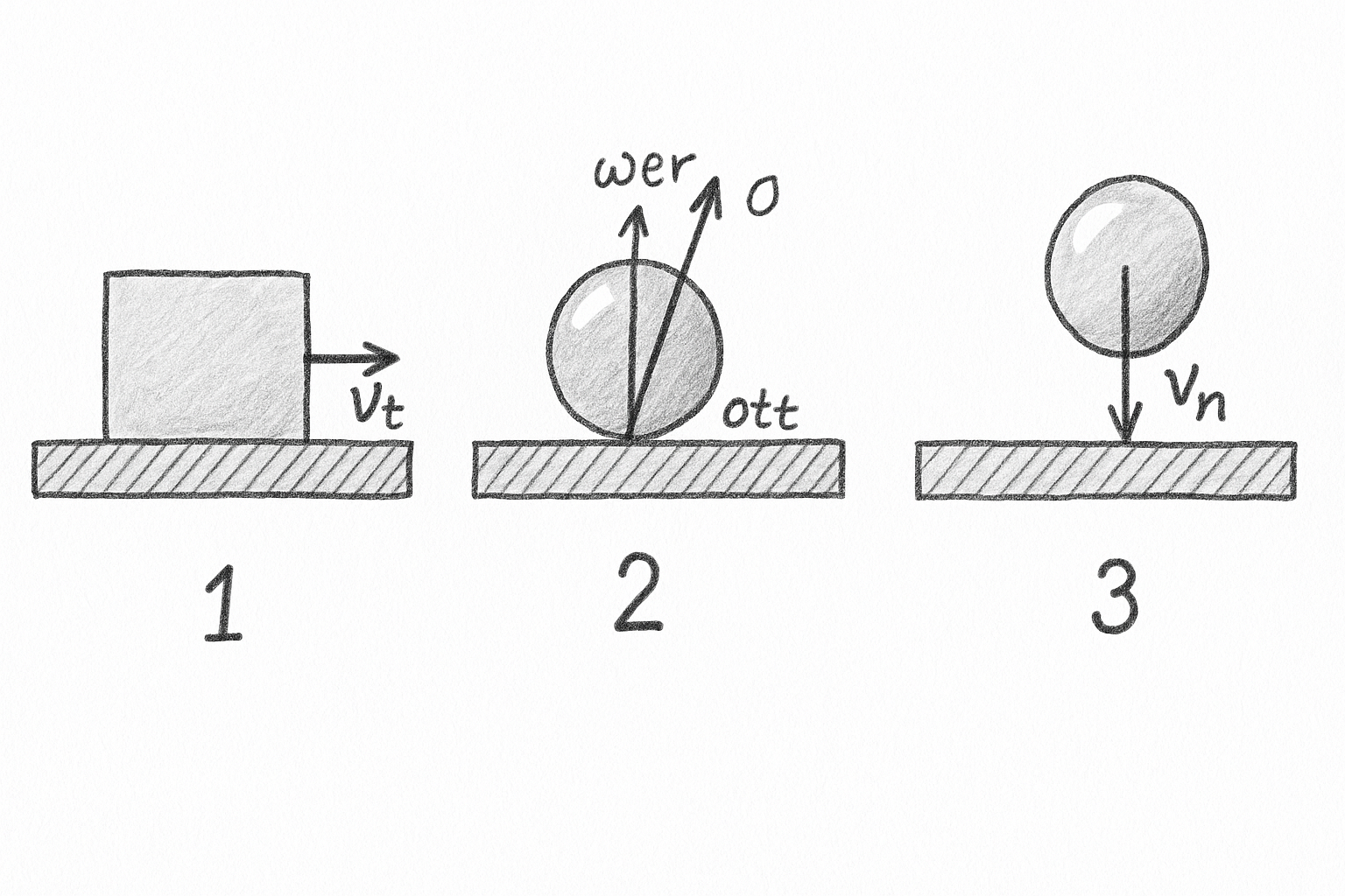
Contacts From a kinematic point of view, there are three main contacts that occur between bodies. -1- Sliding contacts For example, a disc brake, a plain bearing, or a wheel inside a bushing. -2- Rolling contacts Examples include a tire rolling on the road, a ball bearing, or a roller bearing. -3- Impact Contacts For example, gears with backlash meshing, punching a sheet of metal, a ball hitting a wall, or a piston hitting a valve.
Below is an image that summarizes the three contacts described above.
Contact Geometry Let's start by clarifying that to create kinematic pairs, we can create form or force couplings. Form couplings are closed-form couplings, while force couplings are open-form couplings. Now let's define contact geometry. This is a fundamental concept when we talk about design and kinematic pairs. There are three possible contact geometries. -1- Point contacts, such as a ball bearing. -2- Linear contacts, such as a roller bearing. -3- Surface contacts, such as a screw-nut connection.
Below is an image to better clarify the three possible contact geometries.
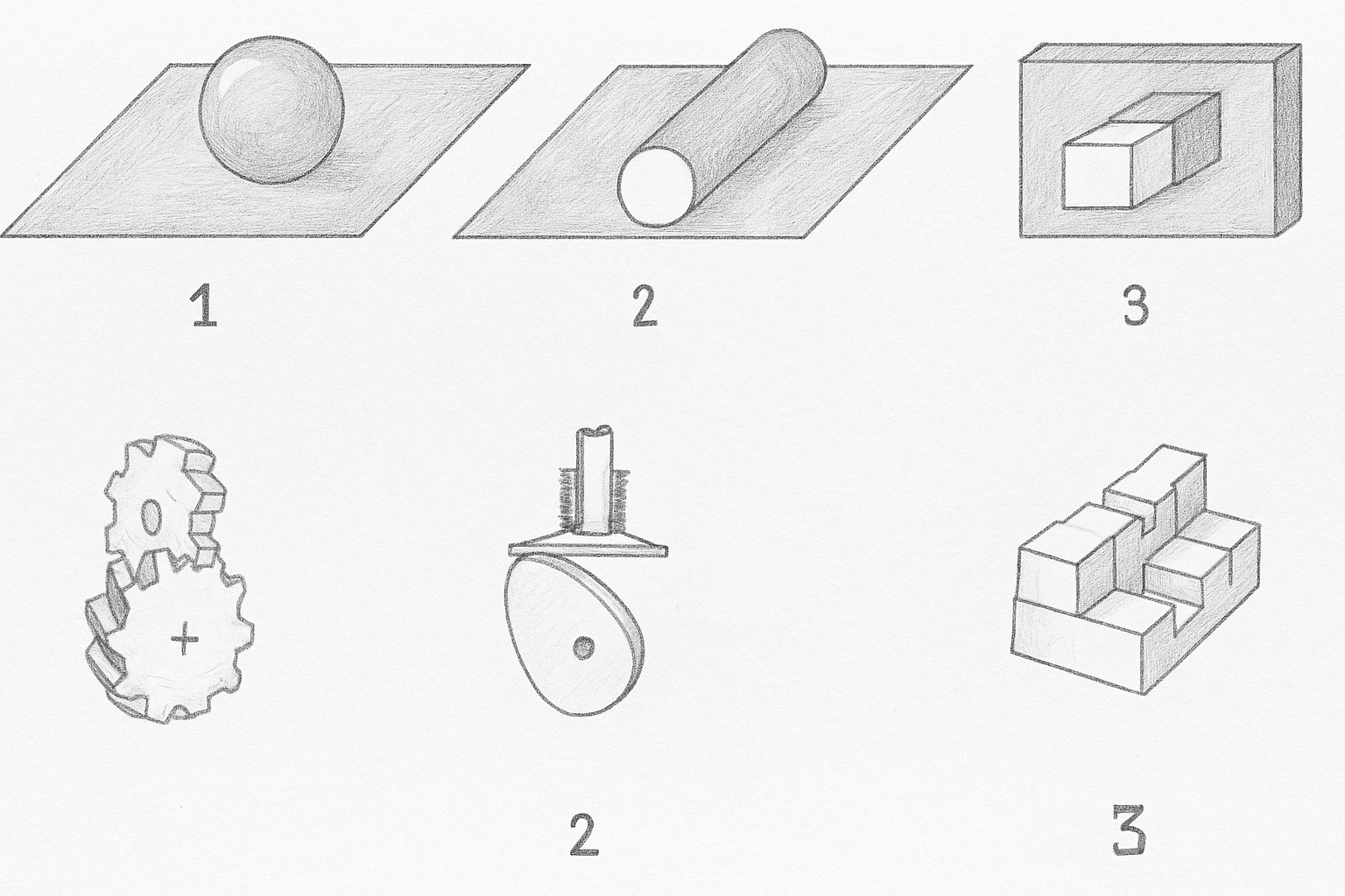
Image created with artificial intelligence, the software used is ChatGPT
Higher and lower torques Higher kinematic torque and lower kinematic torque are two distinctions that must be made. In higher-order pairs, contact is point-like or linear, and therefore more limited and less constraining. In lower-order pairs, contact occurs on extended, mating surfaces (for example, a cylinder inside a hole).
Some Notes Regarding contact geometry, an example of surface or mating contact is the screw-lead contact. The revolving or hinge pair can be formed with either sliding or rolling contacts. An example of a higher-order kinematic pair is the flat cam. Pairs formed with mating contacts, pairs formed between non-rigid members, and pairs formed with surface contacts are not higher-order kinematic pairs. Let's clarify the concept of a higher-order kinematic pair. A higher-order kinematic pair is a type of connection between two rigid bodies that allows relative motion between them, but with point-like or linear contacts, not with mating surfaces. Elementary or lower-order pairs are formed through surface or mating contacts. In relation to contact geometry, an example of point contact is sphere-on-plane contact. And finally, we can say that... The relative displacement between two bodies connected by a kinematic pair can be achieved with different pairs of conjugated surfaces.
Conclusions When we talk about kinematic pairs, it means we're tackling a project, and to design something well, we absolutely must understand kinematic pairs. Our mechanical system will function better and longer if we identify the right kinematic pair to create mechanical motion. We can say that kinematic pairs are the heart of motion transmission; they define which motions are permitted and how many degrees of freedom are present in the mechanical system we're designing.
Question It's difficult to attribute the idea of kinematic pairs to a single inventor, but we can attribute it to the German mechanical engineer Franz Reuleaux (1829-1905). Did you know that Reuleaux is considered the father of machine kinematics? Did you know that he was the first to conceptualize kinematic pairs in a systematic way?

ITALIAN

13-08-2025 - Meccanica - Coppie cinematiche [EN]-[IT] Con questo post vorrei dare una breve istruzione a riguardo dell’argomento citato in oggetto (code notes: X_94)
Coppie cinematiche
immagine creata con l’intelligenza artificiale, il software usato è ChatGPT
Introduzione
Oggi introduciamo il concetto di coppia cinematica. In meccanica applicata le coppie cinematiche sono dei dispositivi di collegamento che consentono un moto relativo fra due corpi, ma impongono vincoli che limitano i loro gradi di libertà reciproci. Possono essere coppie cinematiche: - Un giunto rotante - Un giunto traslante - Una coppia elicoidale - Una coppia sferica - Una coppia cilindrica - Una coppia prismatica - Una guida a pattino - Una guida volvente
Possiamo anche dire così, che si definisce coppia il sistema formato da 2 membri contigui collegati: se tra di essi esiste un movimento relativo (cioè il sistema ha almeno 1 grado di libertà) si ha una coppia cinematica.
Qui di seguito un immagine con l'esempio di una coppia prismatica, una guida a pattino, una guida volvente
immagine creata con l’intelligenza artificiale, il software usato è ChatGPT
I contatti Dal punto di vista cinematico esistono tre contatti principali che avvengono tra i corpi. -1- Contatti di strisciamento Ad esempio un freno a disco, un cuscinetto a strisciamento o una ruota all'interno di una boccola. -2- Contatti di rotolamento Possono essere degli esempi lo pneumatico che rotola sulla strada, un cuscinetto a sfere o un cuscinetto a rulli. -3- Contatti d'urto A esempio Ingranaggi con gioco che si innestano, punzonatura di una lamiera, una palla che colpisce una parete o un pistone che colpisce la valvola.
Qui di seguito un immagine che riassume i tre contatti descritti sopra.
La geometria di contatto Partiamo con il chiarire che per realizzare le coppie cinematiche possiamo creare accoppiamenti di forma o di forza. Gli accoppiamenti di forma sono in forma chiusa, gli accoppiamenti di forza sono in forma aperta. Ora definiamo la geometria di contatto. Questo è un concetto fondamentale quando parliamo di progettazione e di coppie cinematiche. Le geometrie di contatto possono essere tre. -1- Contatti puntiformi come ad esempio un cuscinetto a sfera. -2- Contatti lineari come ad esempio un cuscinetto a rulli. -3- Contatti superficiali come ad esempio vite-madrevite
Qui di seguito un immagine per provare a chiarire meglio le tre geometrie di contatto possibili.
immagine creata con l’intelligenza artificiale, il software usato è ChatGPT
Coppie superiori e coppie inferiori Coppia cinematica superiore e coppia cinematica inferiore sono due distinzioni da fare. Nelle coppie superiori, il contatto è puntiforme o lineare, quindi più limitato e meno vincolante. Nelle coppie inferiori, il contatto avviene su superfici estese e combacianti (può essere un esempio un cilindro dentro un foro).
Alcune note In relazione alla geometri di contatto, è un esempio di contatto superficiale o di combaciamento il contatto vite madrevite. La coppia rotoidale o cerniera può essere realizzata sia con contatti di strisciamento che con contatti di rotolamento. Un esempio di coppia cinematica superiore è la camma piana. Le coppie realizzate con contatti di combaciamento, le coppie realizzate tra membri non rigidi, le coppie realizzate con contatti di superficie non sono coppie cinematiche superiori. Chiariamo il concetto di coppia cinematica superiore. Una coppia cinematica superiore è un tipo di collegamento tra due corpi rigidi che consente un movimento relativo tra di essi, ma con contatti puntiformi o lineari, e non con superfici combacianti. Le coppie elementari o inferiori sono realizzate tramite contatti superficiali o di combaciamento. In relazione alla geometri di contatto, è un esempio di contatto puntiforme contatto sfera su piano. E per ultimo possiamo dire che... Lo spostamento relativo fra 2 corpi connessi tramite una coppia cinematica può essere ottenuto con differenti coppie di superfici coniugate.
Conclusioni Quando parliamo di coppie cinematiche vuol dire che stiamo affrontando un progetto e per progettare bene qualcosa dobbiamo assolutamente conoscere le coppie cinematiche. Il nostro sistema meccanico funzionerà meglio e più a lungo se individuiamo la giusta coppia cinematica con cui creare un movimento meccanico. Possiamo dire che le coppie cinematiche sono il cuore della trasmissione del moto, esse definiscono quali movimenti sono permessi e quanti gradi di libertà sono presenti nel sistema meccanico che stiamo progettando.
Domanda Difficile attribuire ad un singolo inventore l'idea delle coppie cinematiche, ma possiamo parlare dell'ingegnere meccanico tedesco Franz Reuleaux (1829-1905). Lo sapevate che Reuleaux è considerato il padre della cinematica delle macchine? Lo sapevate che le coppie cinematiche furono concettualizzate in forma sistematica proprio da lui per la prima volta?
THE END