~~~ La versione in italiano inizia subito dopo la versione in inglese ~~~
ENGLISH

19-08-2025-Mechanical Measurements - Static Calibration [EN]-[IT] With this post, I would like to provide a brief introduction to the topic in question. (code notes: X-86)
Static Calibration

Image created with artificial intelligence, the software used is Microsoft Copilot
Introduction consists of comparing the readings of a measuring instrument with known values under static conditions, i.e., without variations over time or movement.
Static calibration is performed for instruments that will measure objects that do not change; that is, the quantity being measured will not change during the measurement.
Report on Static Calibration Let's consider a spring dynamometer that measures a force applied to the dynamometer itself. Let's identify the input force as Pi, while the output is represented by the displacement Xo.
Constructing the Force vs. Displacement Graph Let's assume we take 12 measurements, initially applying a force of 1 N. Therefore, Pi1 will be 1 N, Pi2 will be 2 N, and so on. For each different input, we will therefore have different outputs, and these are all summarized in the table below.
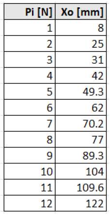
At this point, we can construct the static calibration graph of the dynamometer by representing the relationship between the applied force Pi and the measured displacement Xo. To construct the graph, we will insert the applied force Pi in Newtons [N] on the X-axis and the displacement Xo in millimeters [mm] on the Y-axis.
Below is the graph. Scattering
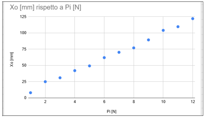
Image created with artificial intelligence, Microsoft Copilot software used
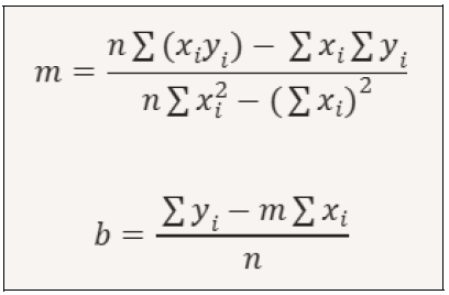
The interpolating line The interpolating line can be added after calculating the linear regression. The line can be drawn by performing the following mathematical operation.
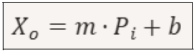
To find the linear regression line, we need to work with the following equation:
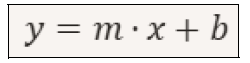
Where: x = is the independent variable (in this case, the force 𝑃𝑖) y = is the variable dependent (the displacement 𝑋𝑜) m = is the slope (slope of the line) b = is the intercept (value of 𝑦 when 𝑥 = 0) To calculate m and b, we can use the following formulas:
Below is the graph with the calculated interpolating line superimposed on the previously calculated graph. Built
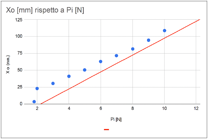
Image created with artificial intelligence, the software used is Microsoft Copilot
The Purpose of Static Calibration This type of calibration serves to: -establish a relationship between the input and output of the system we are analyzing -determine the sensitivity of the transducer -evaluate systematic errors. Conclusions Static calibration is a fundamental process for correctly identifying how a measurement system behaves. The purpose of static calibration is to determine the relationship between the physical input and the measured output. In the case we examined, the input was a force and the output was displacement. This process provides precision in practical applications by reducing systematic errors.
Question Did you know that static calibration has evolved primarily thanks to the development of international standards such as ISO? Did you know that today, static calibration is considered correct only if performed in accordance with ISO standards?

ITALIAN

19-08-2025-Misure meccaniche - La taratura statica [EN]-[IT] Con questo post vorrei dare una breve istruzione a riguardo dell’argomento citato in oggetto (code notes: X-86)
La taratura statica
immagine creata con l’intelligenza artificiale, il software usato è Microsoft Copilot
Introduzione consiste nel confrontare le letture di uno strumento di misura con valori noti in condizioni statiche, cioè senza variazioni nel tempo o di movimento. La taratura statica viene eseguita per strumenti che andranno a misurare oggetti che non mutano, cioè la grandezza da misurare non cambierà durante la misurazione.
Relazione sulla taratura statica Consideriamo un dinamometro a molla che debba misurare una forza applicata al dinamometro stesso. Identifichiamo come Pi la forza d’ingresso, mentre l’uscita è rappresentata dallo spostamento Xo.
Costruzione del grafico forza vs spostamento Consideriamo di fare 12 misure, applicando all’inizio una forza di 1 N, quindi Pi1 sarà 1N, Pi2 sarà 2N e così via. Ad ogni ingresso diverso avremo quindi delle uscite diverse e questi sono raccolti tutti nella tabella sottostante.
A questo punto possiamo costruire il grafico della taratura statica del dinamometro rappresentando la relazione tra la forza applicata Pi e lo spostamento misurato Xo Per costruire il grafico inseriremo sull’asse X la forza applicata Pi in Newton [N] e sull’asse Y lo spostamento X0 in millimetri [mm]
Qui di seguito il grafico a dispersione
immagine creata con l’intelligenza artificiale, il software usato è Microsoft Copilot
La retta interpolante La retta interpolante può essere aggiunta dopo aver calcolato la regressione lineare. La retta può essere disegnata eseguendo la seguente operazione matematica.
Per trovare la retta di regressione lineare bisogna lavorare sulla seguente equazione:
Dove: x=è la variabile indipendente (in questo caso la forza 𝑃𝑖) y=è la variabile dipendente (lo spostamento 𝑋𝑜) m=è il coefficiente angolare (pendenza della retta) b=è l’intercetta (valore di 𝑦 quando𝑥=0) Per calcolare m e b possiamo usare le seguenti formule
Qui di seguito il grafico con la retta interpolante calcolata e sovrapposta ai grafico precedentemente costruito
immagine creata con l’intelligenza artificiale, il software usato è Microsoft Copilot
La finalità della taratura statica Questa tipologia di taratura serve: -a stabilire una relazione tra ingresso-uscita del sistema che stiamo analizzando -a determinare la sensibilità del trasduttore -a valutare errori sistematici. Conclusioni La taratura statica è un processo fondamentale per identificare correttamente come si comporta un sistema di misura. Il fine della taratura statica è determinare la relazione tra l'ingresso fisico e l’uscita misurata. Nel caso che abbiamo esaminato l’ingresso era una forza e l’uscita lo spostamento. Questo processo fornisce precisione nelle applicazioni pratiche riducendo gli errori sistematici.
Domanda Lo sapevate che la taratura statica si è evoluta principalmente grazie allo sviluppo di normative internazionali come le ISO? Lo sapevate che oggi la taratura statica viene considerata corretta solo se eseguita in conformità alle normative ISO?
THE END